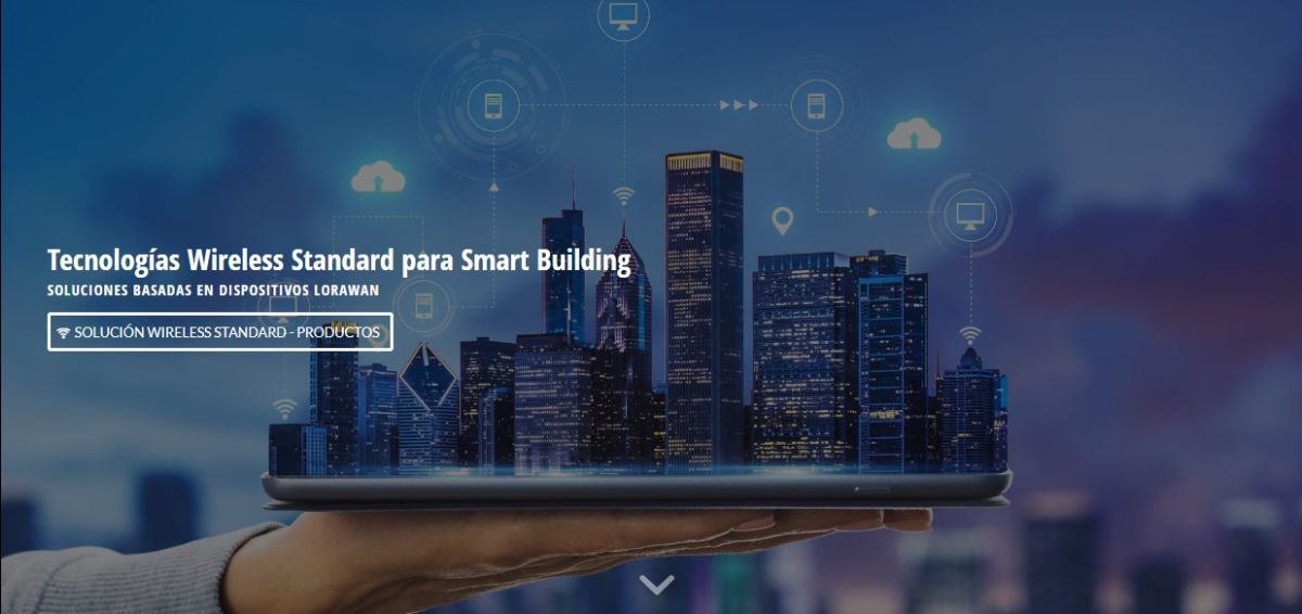
LEZ – Low Emission Zones for smart cities and urban areas
 para ciudades inteligentes y áreas urbanas")
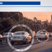
A low emissions zone (LEZ) is an urban area in which vehicle access, circulation and parking restrictions are applied to improve air quality and mitigate greenhouse gas emissions , in accordance with the classification of vehicles by its emissions level in accordance with the provisions of the current General Vehicle Regulations.
Law 7/2021, of May 20, on climate change and energy transition establishes that municipalities with more than 50,000 inhabitants, municipalities with more than 20,000 inhabitants when the limit values of the pollutants regulated in Royal Decree 102/2011 are exceeded. , of January 28 and the island territories will adopt sustainable urban mobility plans before 2023.
These zones are delimited by specific signs and apply access, circulation and parking restrictions to vehicles according to their environmental label.
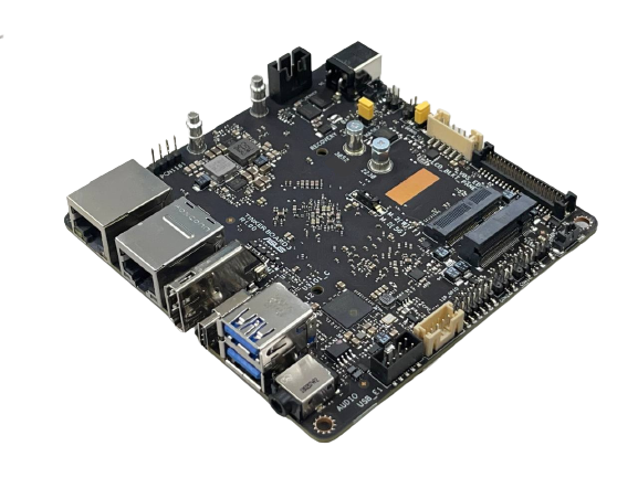
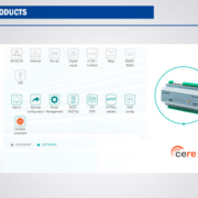
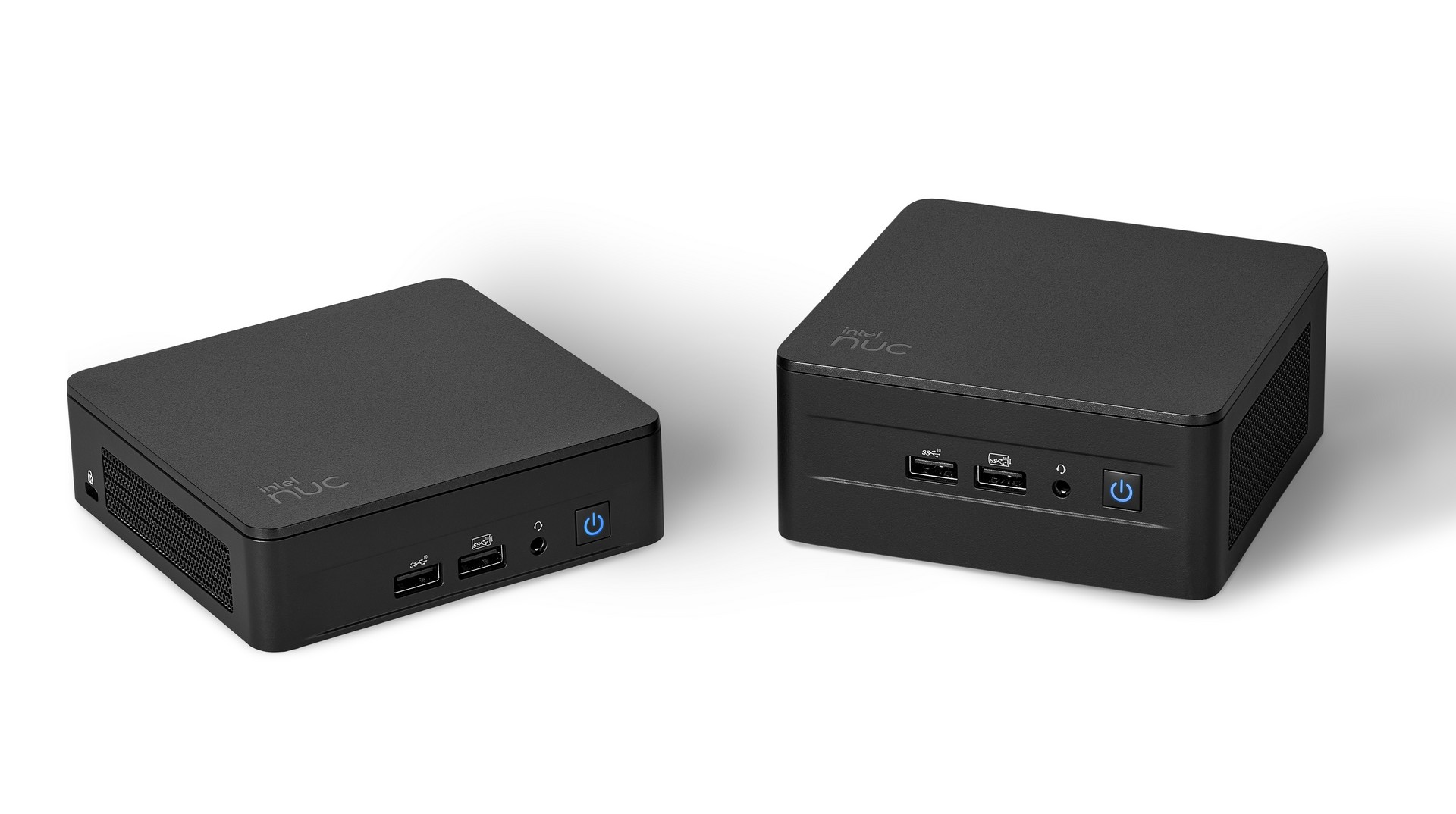
Matrix Electrónica in collaboration with our partners offers a range of products to efficiently manage EPZs, improving their effectiveness and efficiency.
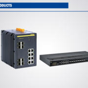
Our products include:
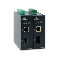
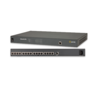
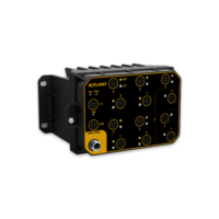
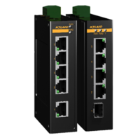
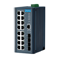
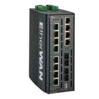
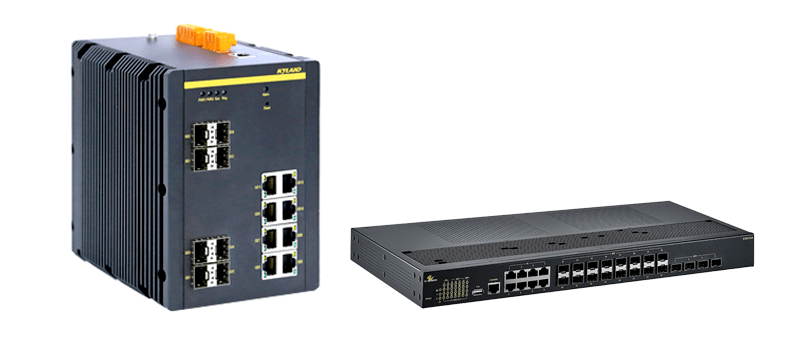
- Access control: Switches and sensors identify vehicles that comply with restrictions and allow them access to the EPZ.
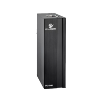
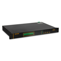
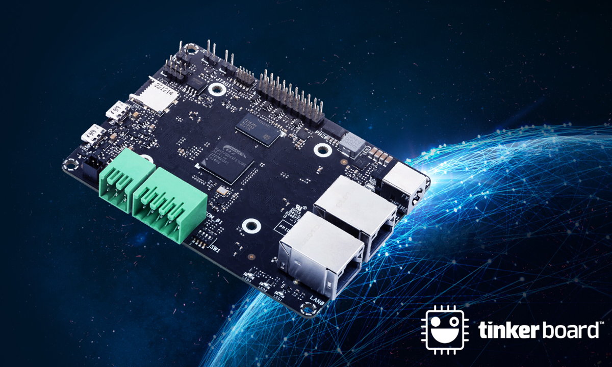
- Mobility management: Sensors and industrial computers collect traffic data in EPZs and optimise vehicle circulation.
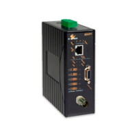
- Air quality: Sensors collect data on air quality in the EPZ and assess the impact of restrictions..
If you are interested in finding out more about our ZBE products, please visit the web section or contact us.


 What is a Switch?